 |
| Medium Tank M3, Fort Knox, June 1942. |
The Medium Tank M3 was an American tank used during World
War II. In Britain the tank was called by two names based on the turret
configuration. Tanks employing US pattern turrets were called the
"Lee," named after Confederate General Robert E. Lee. Variants using
British pattern turrets were known as "Grant," named after U.S.
General Ulysses S. Grant.
Design commenced in July 1940 and the first M3s were
operational in late 1941. The U.S. Army needed a good tank and coupled with the
United Kingdom's demand for 3,650 medium tanks immediately, the Lee began
production by late 1940. The design was a compromise meant to produce a tank as
soon as possible. The M3 had considerable firepower as it was well armed and
provided good protection, but had certain serious drawbacks in its general
design and shape, such as: a high silhouette, an archaic sponson mounting of
the main gun, riveted construction, and poor off-road performance. Its overall
performance was not satisfactory and the tank was withdrawn from front line
duty — except in the remote areas of the Asian Theater where it was used by
British forces as late as mid-1944 or later — as soon as the M4 Sherman became
available in large numbers. In spite of this it was considered by Hans von Luck
superior to the best German tank at the time of its introduction, the Panzer
IV.
In 1939, the U.S. Army possessed approximately 400 tanks,
mostly M2 Light Tanks, with 18 of the to-be-discontinued M2 Medium Tanks as the
only ones considered "modern." The U.S. funded tank development
poorly during the interwar years, and had no infrastructure for production,
little experience in design, and poor doctrine to guide design efforts.
The M2 medium tank was typical of armored fighting vehicles
(AFVs) many nations produced in 1939. When the U.S. entered the war, the M2
design was already obsolete with a 37 mm gun, 32 mm frontal armor, excessive
machine gun secondary armament and a very high silhouette. The Panzer III and
Panzer IV's success in the French campaign led the U.S. Army to order
immediately a new medium tank armed with a 75 mm gun in a turret. This would be
the M4 Sherman. Until the Sherman reached production, an interim design with a
75 mm gun was urgently needed.
The M3 was the solution. The design was unusual because the
main weapon — a larger caliber, low-velocity 75 mm gun — was in an offset
sponson mounted in the hull with limited traverse. (The sponson mount was
necessary because at the time American tank plants were incapable of casting a
turret big enough to hold the 75mm main gun). A small turret with a lighter,
high-velocity 37 mm gun sat on the tall hull. A small cupola on top of the turret
held a machine gun. The use of two main guns was seen on the French Char B, the
Soviet T-35, and the Mark I version of the British Churchill tank. In each
case, two weapons were mounted to give the tanks adequate capability in firing
both anti-personnel high explosive ammunition and armor-piercing ammunition for
anti-tank combat. The M3 differed slightly from this pattern having a main gun
which could fire an armor-piercing projectile at a velocity high enough for
efficiently piercing armor, as well as deliver a high-explosive shell that was
large enough to be effective. Using a hull mounted gun, the M3 design could be
produced faster than a tank featuring a turreted gun. It was understood that
the M3 design was flawed, but Britain urgently needed tanks.
The M3 was tall and roomy: the power transmission ran
through the crew compartment under the turret cage to the gearbox driving the
front sprockets. Steering was by differential braking, with a turning circle of
37 ft (11 m). The vertical volute-sprung suspension (VVSS) units possessed a
return roller mounted directly atop the main housing of each of the six
suspension units (three per side), designed as self-contained and readily
replaced modular units bolted to the hull sides. The turret was power-traversed
by an electro-hydraulic system in the form of an electric motor providing the
pressure for the hydraulic motor. This fully rotated the turret in 15 seconds.
Control was from a spade grip on the gun. The same motor provided pressure for
the gun stabilizing system.
The 75-mm was operated by a gunner and a loader. Sighting
the 75-mm gun used an M1 periscope — with an integral telescope — on the top of
the sponson. The periscope rotated with the gun. The sight was marked from zero
to 3,000 yd (2,700 m) with vertical markings to aid deflection shooting at a
moving target. The gunner laid the gun on target through geared handwheels for
traverse and elevation.
The 37-mm was aimed through the M2 periscope, though this
was mounted in the mantlet to the side of the gun. It also sighted the coaxial
machine gun. Two range scales were provided: 0-1,500 yd (1,400 m) for the 37-mm
and 0-1,000 yd (910 m) for the machine gun.
Though not at war, the U.S. was willing to produce, sell and
ship armored vehicles to Britain. The British had requested that their Matilda
and Crusader tank designs be made by American factories, but this request was
declined. With much of their equipment left on the beaches near Dunkirk, the
equipment needs of the British were acute. Though not entirely satisfied with
the design, they ordered the M3 in large numbers. British experts had viewed
the mock-up in 1940 and identified features which they considered flaws — the
high profile, the hull mounted main gun, the lack of a radio in the turret (though
the tank did have a radio down in the hull), the riveted armor plating (whose
rivets tended to pop off inside the interior in a deadly ricochet when the tank
was hit by a non-penetrating round), the smooth track design, insufficient
armor plating and lack of splash-proofing of the joints. The British desired
modifications for the tank they were purchasing, including the turret being
cast rather than riveted. A bustle was to be made at the back of the turret to
house the Wireless Set No. 19 radio. The tank was to be given thicker armor
plate than the original U.S. design, and the machine gun cupola was to be
replaced with a simple hatch. With these modifications accepted the British
ordered 1,250 M3s. The order was subsequently increased with the expectation
that when the M4 Sherman was available it could replace part of the order.
Contracts were arranged with three U.S. companies. The total cost of the order
was approximately 240 million US dollars. This equaled the sum of all British
funds in the US. It took the Lend-Lease act to solve the United Kingdom's
shortfall.
The prototype was completed in March 1941 and production
models followed with the first British specification tanks produced in July.
Both U.S. and British tanks had thicker armor than first planned. The British
design required one fewer crew member than the US version due to the radio in
the turret. The U.S. eventually eliminated the full-time radio operator,
assigning the task to the driver. After extensive losses in Africa and Greece
the British realized that to meet their needs for tanks both the Lee and the
Grant types would need to be accepted.
The U.S. military used the "M" (Model) letter to
designate nearly all of their equipment. When the British Army received their
new M3 medium tanks from the US, confusion immediately set in, as the M3 medium
tank and the M3 light tank were identically named. The British Army began
naming their American tanks after American military figures, although the U.S.
Army never used those terms until after the war. M3 tanks with the cast turret
and radio setup received the name "General Grant," while the original
M3s were called "General Lee," or more usually just "Grant"
and "Lee." The M3 brought much-needed firepower to British forces in
the North African desert campaign.
The chassis and running gear of the M3 design was adapted by
the Canadians for their Ram tank. The hull of the M3 was also used for
self-propelled artillery and recovery vehicles.
Of the 6,258 M3s produced by the U.S., 2,855 M3s were
supplied to the British Army, and about 1,386 to the Soviet Union. The American
M3 medium tank's first action during the war was in 1942, during the North
African Campaign. British Lees and Grants were in action against Rommel's
forces at the Battle of Gazala on 27 May that year. Their appearance was a
surprise to the Germans, who were unprepared for the M3s 75 mm gun. They soon
discovered the M3 could engage them beyond the effective range of their 5 cm
Pak 38 anti-tank gun, and the 5 cm KwK 39 of the Panzer III, their main medium
tank. The M3 was also vastly superior to the Fiat M13/40 and M14/41 tanks
employed by the Italian troops, whose 47 mm gun was effective only at point
blank range, while only the few Semoventi da 75/18 self-propelled guns were
able to destroy it using HEAT rounds. Grants and Lees served with the British
in North Africa until the end of the campaign. Following Operation Torch (the
invasion of French North Africa), the U.S. also fought in North Africa using
the M3 Lee. The U.S. 1st Armored Division had given up their new M4 Shermans to
the British prior to the Second Battle of El Alamein. Subsequently, a regiment
of the division was still using the M3 Lee when they arrived to fight in North
Africa. The M3 was generally appreciated during the North African campaign for
its mechanical reliability, good armor protection and heavy firepower.
In all three areas, the M3 was able to engage German tanks
and towed anti-tank guns. Yet the tall silhouette and low, hull-mounted 75-mm
were tactical drawbacks, since they prevented fighting from a hull-down firing
position. The use of riveted hull superstructure armor on the early versions
led to spalling, where the impact of enemy shells caused the rivets to break
off and become projectiles inside the tank. Later models were built with
all-welded armor to eliminate this problem. These lessons were applied to the
design and production of the M4. The M3 was replaced by the M4 Sherman as soon
as the M4 was available, though several M3s saw limited action in the battle
for Normandy as armored recovery vehicles; their armament replaced with dummy
guns.
As the Soviets used diesel fuel for their tanks, the 1,300
M3A3 and M3A5s were supplied to the USSR with General Motors-built twin diesel
engines. These were supplied through the Lend-Lease program in 1942-1943. All
were Lee variants, although the Soviets sometimes referred to them generically
as Grants. The M3 was unpopular in the Red Army, which already used the more
modern T-34. The faults of the M3 Lee revealed themselves in engagements
against enemy armor and anti-tank weapons; the Soviet tankers gave it the
nickname "a grave for six
men." With the Soviet Union producing close to 1,500 T-34s a month,
their use of the M3 Lee declined after mid-1943. The Soviets still used them on
secondary fronts, such as in the Arctic during the Red Army's Petsamo–Kirkenes
Offensive in October 1944.
The Pacific War was an ocean war fought primarily by the
naval fleets of the U.S. and the Empire of Japan. Tank warfare played a
secondary role as the primary battles were between warships and between
aircraft. In the Pacific Ocean Theater and Southwest Pacific Theater, the U.S.
Army deployed only a third of its 70 separate tank battalions, and none of its
armored divisions, while the U.S. Marine Corps deployed all six of its tank
battalions.
When the British Army received M4 Shermans, about 900 M3
tanks were transferred to the Indian Army and some of these saw action in the
war in South East Asia. British Lees and Grants were used by the British
Fourteenth Army until the fall of Rangoon, performing "admirably" in
Burma in 1944-45, in its original role: supporting infantry. In the Far East,
the M3's main task was infantry support. It played a pivotal role during the
Battle of Imphal, during which the Imperial Japanese Army's 14th Tank Regiment
(consisting of mostly captured British M3 Stuart light tanks and their own Type
95 Ha-Go light tanks) encountered M3 medium tanks for the first time and found
itself outgunned and outmatched by the British armor. Despite their
lower-than-average off-road performance, the M3s performed well as they
traversed the steep hillsides around Imphal. Officially declared obsolete in
April 1944, the Lee nevertheless saw action until the end of the war.
The Australian Army also received approximately 1,700 M3
Grants that had originally been part of a UK order. The Australian Armoured
Corps had been formed in 1941 to take part in the North African Campaign, but
was retained in Australia after the outbreak of hostilities with Japan. In
1941–42, the cadres of three armored divisions were formed – all of them were
equipped partly with the M3 Grant – in addition to M3 Stuart light tanks. In
April and May 1942, the 1st Armoured Division's regiments began re-equipping
with M3 Grants and completed their training in a series of large exercises
around Narrabri, New South Wales. The 2nd and 3rd Armoured Divisions were
officially formed in 1942 and were also partly equipped with M3 Grants. In
January 1943, the main body of the 1st Armoured Division was deployed to home
defense duties between Perth and Geraldton, Western Australia, where it formed part
of III Corps. However, the Grants were deemed unsuitable for combat duties
overseas and M3 units were re-equipped with the Matilda II service before being
deployed to the New Guinea and Borneo Campaigns. Due to personnel shortages,
all three divisions were officially disbanded during 1943 and downgraded to
brigade- and battalion-level units.
During the battle for Tarawa island in 1943, the US Army
attacked nearby Makin Island, which was considered a less costly operation. The
army was supported by a platoon of M3A5 Lee medium tanks from the US Army's
193rd Tank Battalion, making this battle the only combat use of the M3 by
America in the Pacific Theater. The US Marine Corps did not use M3 Lees; their
light tank battalions were equipped with M3 Stuarts until they were replaced by
M4 Shermans in mid-1944.
During the war, the Australian Army had converted some M3
Grants for special purposes, including a small number of bulldozer variants,
beach armored recovery vehicles and wader prototypes.
Following the end of the war 14 of the Australian Grants
were converted to a local self-propelled gun design, the Yeramba, becoming the
only SPG ever deployed by the Australian Army. Fitted with a 25-pounder field
gun, the Yerambas remained in service with the 22nd Field Regiment, Royal
Australian Artillery, until the late 1950s.
Many M3s deemed surplus to Australian Army requirements were
acquired by civilian buyers during the 1950s and 1960s for conversion to
earthmoving equipment and/or tractors.
Overall, the M3 was able to cope with the battlefield of
1942. Its armor and firepower were the equal or superior to most of the threats
it faced, especially in the Pacific. Long-range, high velocity guns were not
yet common on German tanks in the African theater. However, the rapid pace of
tank development meant that the M3 was very quickly outclassed. By mid-1942,
with the introduction of the German Tigers, the up-gunning of the Panzer IV to
a long 75-mm gun, and the first appearance in 1943 of the Panthers, along with
the availability of large numbers of Shermans, the M3 was withdrawn from
service in the European Theater.
In the 1943 movie Sahara,
starring Humphrey Bogart, the character's main form of transportation was an M3
Lee named "Lulu Belle"; the same is true of the 1995 remake starring
Jim Belushi. The 1995 remake used a similar M3 Grant lookalike.
In Season 1 Episode 2 (Hold That Tiger) of Hogan's Heroes, the Tiger tank is
actually an M3 Lee.
In the 1979 Steven Spielberg movie 1941, starring Dan Akroyd and John Belushi, an M3 Lee is a featured
element.
Specifications
Type: Medium tank
Place of origin:
United States
Wars: World War
II
Produced: August
1941 – December 1942
Number built:
6,258
Weight: 30 short
tons (27 t)
Length: 18 ft 6
in (5.64 m)
Width: 8 ft 11 in
(2.72 m)
Height: 10 ft 3
in (3.12 m) – Lee
Crew: 7 (Lee); 6
(Grant)
Armor:
51 mm (hull front, turret front,
sides, and rear)
38 mm (hull sides and rear)
Main armament:
1 × 75 mm Gun M2/M3 in hull; 46
rounds
1 × 37mm Gun M5/M6 in turret; 178
rounds
Secondary armament:
2-3–4 × .30-06 Browning M1919A4 machine guns; 9,200 rounds
Engine: Wright
(Continental) R975 EC2; 400 hp (300 kW)/340 hp (250 kW)
Transmission:
Mack Synchromesh, 5 speeds forward, 1 reverse
Suspension:
vertical volute spring
Ground clearance:
18 in (0.46 m)
Fuel capacity:
662 liters (175 US gallons)
Operational range:
193 km (119 mi)
Speed: 26 mph (42
km/h) (road); 16 mph (26 km/h) (off-road)
Steering system:
Controlled differential
Variants
U.S. Variants
M3 (Lee I/Grant I): Riveted
hull, high profile turret, gasoline engine. 4,724 built.
M3A1 (Lee II): Cast
(rounded) upper hull. 300 built.
M3A2 (Lee III): Welded
(sharp edged) hull. Only 12 vehicles produced.
M3A3 (Lee IV/Lee V): Twin
GM 6-71 diesel variant of welded hull. Side doors welded shut or eliminated.
322 built.
M3A4 (Lee VI): Stretched
riveted hull, 1 x Chrysler A-57 Multibank engine, made up of five 4.12 liter
displacement, 6-cyl L-head car engines (block upwards) mated to a common
crankshaft, displacement 21 liters, 470 hp at 2,700 rpm. Side doors eliminated.
109 built.
M3A5 (Grant II): Twin
GM 6-71 diesel variant of riveted hull M3. Although it had the original Lee
turret and not the Grant one, was referred by the British as Grant II. 591
built.
M31 Tank Recovery
Vehicle (Grant ARV I): Based on M3 chassis, with dummy turret and dummy 75
gun. A 60,000 lb (27,000 kg) winch installed.
M31B1 Tank Recovery
Vehicle: Based on M3A3.
M31B2 Tank Recovery
Vehicle: Based on M3A5.
M33 Prime Mover: M31
TRV converted to the artillery tractor role, with turret and crane removed. 109
vehicles were converted in 1943-44.
105 mm Howitzer Motor
Carriage M7 (Priest): 105 mm M1/M2 howitzer installed in open
superstructure. A gunless version was used as an OP (observation post vehicle)
155 mm Gun Motor
Carriage M12: Designed as the T6. A 155 mm howitzer on M3 chassis. 100
built in 1942-1943. M30 Cargo Carrier on same chassis to transport gun crew and
ammunition.
British Variants
Grant ARV: Grant
I and Grant UK models with guns removed and replaced with armored recovery
vehicle equipment.
Grant Command: Grant
fitted with map table and extra radio equipment and having guns removed or
replaced with dummies.
Grant Scorpion III: Grant
with 75 mm gun removed, and fitted with Scorpion III mine flail, few made in
early 1943 for use in North Africa.
Grant Scorpion IV: Grant
Scorpion III with additional motor to increase Scorpion flail power.
Grant CDL: From
"Canal Defence Light"; Grants with the 37 mm gun turret replaced by a
new turret containing a powerful searchlight and a machine gun. 355 were also
produced by the Americans, who designated it the Shop Tractor T10.
Australian Variants
M3 BARV: A single
M3A5 Grant tank was converted into a "Beach Armoured Recovery
Vehicle."
Yeramba Self Propelled Gun: Australian SP 25 pounder. 13 vehicles
built in 1949 on M3A5 chassis in a conversion very similar to the Canadian
Sexton.
 |
| Early production model M3 Medium Tank. |
 |
| Medium Tank M3A1. |
 |
| M3A1 Medium Tank. |
 |
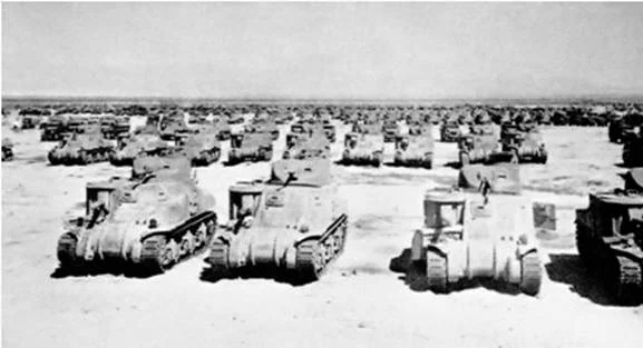
| M3 Medium Tanks, England, 1942. |
 |
| Aside from the 1st Armored Division, the only other U.S. unit to use the M3 Medium Tank in combat in Tunisia was the 751st Tank Battalion that supported the 34th Infantry Division. This unit painted large tactical numbers edged in white on the rear of their turrets as seen here. Tunisia, February 1943. |
 |
| M3 Medium Tank in repair depot. |
 |
| M3 Medium Tank, 1st Armored Division, Tunisia, November 1942. |
 |
| M3 Medium Tank, "Kentucky," North Africa, 1942. |
 |
| Crew of Medium Tank M3 (309490), D Company, 2nd Battalion, 12th Armored Regiment, 1st Armored Division, Souk el Arba, Tunisia. 23 November 1942. |
 |
| Crew of M3 Medium Tank (309503), 2nd Battalion, 12th Artillery Regiment, 1st Armored Division, Souk el Arba, Tunisia, November 1942. |
 |
| M3 Medium Tank, 1st Armored Division, Tunis. |
 |
| M3 Medium Tank on 50-ton Raft, Medium M1, circa March 1942. |
 |
| M3 Medium Tanks on Butaritari. A medical team waits beside their jeep for the tanks to pass. |
 |
| Medium Tank M3. |
 |
| M3 medium tank during training. |
 |
| M3 medium tanks with other vehicles, Iron Mountain, California. |
 |
| M3 medium tank during training. |
 |
| M3 medium tank during training. |
 |
| Crewman of an M3 medium tank on washday during training in the desert. |
 |
| Crewmen of an M3 medium tank dig a slit trench in the desert during training. |
 |
| The tank commander of an M3 medium tank takes a drink of water from a lister bag. |
 |
| The crewman of an M3 medium tank prepares a meal in the desert during training. |
 |
| M3 medium tanks. |
 |
| M3 Medium Tank. |
 |
| M3A1 Medium Tank. |
 |
| Late production M3 Medium Tank. |
 |
| M3s during maneuvers in England, 1942. |
 |
| M3s during maneuvers in England, 1942. |
 |
| M3 medium tank. |
 |
| M3 medium tank. |
 |
| M3 medium tank. |
 |
| Interior of M3 medium tank. |
 |
| Wooden mock-up of M3 medium tank. |
 |
| Crewman drinks water from a canteen in front of his M3 medium tank. |
 |
| M3, Fort Knox, Kentucky. |
 |
| Soldiers recover a M3 medium tank from the Cumberland River, 19 October 1942, after it sank during an attempted crossing. |
 |
| M3 medium tanks, Fort Benning, Georgia. |
 |
| M3 medium tank, Fort Knox, Kentucky. |
 |
| M3 medium tank after being struck by a train, U.S. southwest. |
 |
| Repairing an M3 medium tank at night. |
 |
| Ordnance men repairing the engine of an M3 medium tank. |
 |
| Crewmen load ammunition for the .30-caliber machine gun into an M3 medium tank. |
 |
| Medium Tank M3. |
 |
| Appliqué plate. A cast armor plate of 44mm thickness conforming to the shape of the final drive housing of the M3 medium Grant (Diesel) tank was produced to give immunity from attack by Japanese anti-tank guns. |
 |
| Medium Tank (M3) "Grant" with the turret designed for British service, 15 July 1941. |
 |
| M3A3 Medium Tank. |
 |
| M3 medium tanks in North Africa. |
 |
| M3 Lee tanks of the 1st Armored Regiment moving forward to help strengthen the Allied garrison in Kasserine Pass, 20 February 1943. |
 |
| Medium Tank M3A1 "Lee." |
 |
| M3A1 medium tank. |
 |
| M3A1 medium tank. |
 |
| M3A2 medium tank. |
 |
| M3A3 medium tank, with 75mm gun in hull and 37mm gun in turret. |
 |
| M3A5 medium tank. |
 |
| M3A5 medium tank. |
 |
| Medium Tank M3A5 "Lee." |
 |
| M3 medium tank in Soviet service. |
 |
| Medium Tank M3. |
 |
| Chrysler Tank Arsenal. Thousands of rivets are used in the production of one of the huge 38-ton Medium Tank M3. Whenever possible rivets are replaced by welded sections, but throughout much of the tank, as in the side plates on which this riveter is working, the steel plate is too heavy for welding. |
 |
| British M3 Grant (left) and Lee (right) in the Western Desert, 1942, showing differences between the British turret and the original design. Grant and Lee tanks of 'C' Squadron, 4th (Queen's Own) Hussars, 2nd Armoured Brigade, El Alamein position, Egypt, 7 July 1942. |
 |
| A pair of Soviet M3 Lees at the Battle of Kursk. |
 |
| Workers in the huge Chrysler Tank Arsenal near Detroit, putting the tracks on one of the giant M3 Medium Tanks. These rolling arsenals weigh 28 tons, are capable of speeds over 25 miles an hour and are equipped with 75mm field artillery gun and a 37mm anti-aircraft gun, as well as four mounted machine guns and various unmounted arms its crew may carry. The tanks are powered by 400 horsepower Wright Whirlwind aviation engines. |
 |
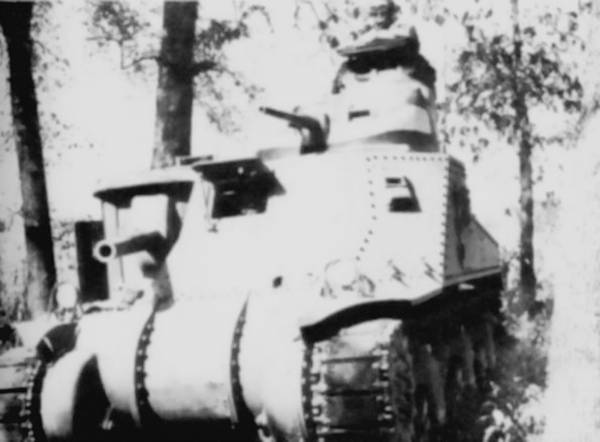
| The riveted construction of the Medium Tank M3 is obvious here. This vehicle is not fitted with stabilization since it lacks counterweights on the 37mm or short 75mm M2 guns. The machine gun in the commander's cupola is present in its right aperture, and one of the driver's hull machine guns has been retained. Track grousers are stored in the box below the driver's hatch, and the tank's siren is positioned below the 75mm gun. Here the crew, Cpl. Larry Corletti, Pvt. Murril Chapman, and Pvt. Louis Robles, practice dismounting from a disabled vehicle. |
 |
| Overhead view of the pilot M3 medium tank. The early production vehicles lacked the rear stowage bins. A towing cable and tools are stowed on the rear deck, and the filler covers for the four fuel tanks can be seen on each side of the engine air intake grille. |
 |
| This early-production tank is fitted with pepperpot-style exhaust mufflers. |
 |
| A cross-section view of the M3 Medium Tank. This tank also has the early exhaust and air cleaner setup. |
 |
| Details of the mounting of the twin hull machine guns are shown in this image. |
 |
| The various components of the 75 mm gun stabilizer are outlined here. |
 |
|
Medium Tank M3 "Lee": The location of the tank's
armament and ammunition stowage is sketched here. The key for the figure is as
follows: 1. Driver's seat. 2. Radio operator's seat. 3. 75-mm
gunner's seat. 4. 37-mm gunner's seat. 5. 37-mm loader's seat. 6. Tank
commander's seat. 8. Cal. .30 machine gun. 9. Cal. .30 machine gun. 10. 37-mm
gun. 11. 75-mm gun. 12. 2
cal. .30 machine guns. 13. Protectoscopes. 14. 51 rounds 37-mm ammunition carried in turret. 15. 13 rounds 37-mm ammunition. 16. 11 rounds 37-mm ammunition. 17. 42 rounds 37-mm ammunition. 18. Ten 100-round belts cal. .30 ammunition. 19. 20 rounds 37-mm ammunition. 20. Fourteen 250-round belts containing 225 rounds
cal. .30 ammunition. 21. Two 250-round belts
containing 225 rounds cal. .30 ammunition. 22. Twenty-five
100-round belts cal. .30 ammunition. 23. 41
rounds 75-mm ammunition; six 100-round belts cal. .30 ammunition. 24. 42 rounds 37-mm ammunition. 25. Submachine gun. 26. Submachine
gun. Carried in tank but not shown on drawing are 9 rounds 75 mm ammunition
carried in cartons and twenty-four 50-round clips cal. .45 ammunition."
|
 |
| M3 and its contribution to other AFVs of the Second World War. |
 |
| The parts of the stabilizer for the 37 mm gun are detailed here. |
 |
| The M3A2 Medium Tank was the first of the series to feature a welded hull. The sharp lines and lack of riveting are obvious. |
 |
| M3A3 Medium Tank was essentially an M3A5 with a welded rather than riveted hull. The sharp lines on the hull of this tank indicates that it has been welded rather than cast. |
 |
| M31 TRV (Tank Recovery Vehicle) showing dummy hull gun. Based on the M3 chassis, with dummy turret and dummy 75 gun. 60,000 lb (27,000 kg) winch installed. In British service was known as the Grant ARV I (Armoured Recovery Vehicle). There was also the M31B1 TRV based on the M3A3 Medium Tank chassis, and the M31B2 TRV based on the M3A5 Medium Tank chassis. |
 |
| A Grant Command variant used by General Montgomery housed at the Imperial War Museum in London. The Grant Command Tank was fitted with a map table and extra radio equipment and having guns removed or replaced with dummies. |
 |
| Grant Dozer in Royal Australian Armoured Corps Tank Museum, Puckapunyal, Victoria, Australia. |
 |
| 75mm gun as mounted in the Medium Tank M3 Lee/Grant in the Royal Australian Armoured Corps Tank Museum, Puckapunyal, Victoria, Australia. |
 |
| Australian M3 BARV (Beach Armoured Recovery Vehicle) in the Royal Australian Armoured Corps Tank Museum, Puckapunyal, Victoria, Australia. Only one vehicle was built, converted from an M3A5 Grant. |
 |
| M3 BARV in Royal Australian Armoured Corps Tank Museum, Puckapunyal, Victoria, Australia. |
 |
| M3 BARV in Royal Australian Armoured Corps Tank Museum, Puckapunyal, Victoria, Australia. |
 |
| 37mm gun as mounted in the M3 Medium Tank Lee/Grant in the Royal Australian Armoured Corps Tank Museum, Puckapunyal, Victoria, Australia. |
 |
|
Medium Tank M3A5 Lee: The legend for this cross-sectional
view is as follows: 1. Oil cooler adapter. 2. Oil cooler. 3. Blower
housing. 4. Blower rotors. 5. Air cleaner. 6. Secondary
fuel filter. 7. Camshaft. 8. Rocker arm. 9. Injector.
10. Injector control rack tube lever. 11. Water outlet manifold. 12.
Exhaust manifold. 13. Balancer shaft. 14. Valve rocker cover. 15. Push
rod. 16. Section of piston and connecting rod. 17. Air box. 18. Solenoid
air inlet control. 19. Air inlet housing. 20. Connecting rod bearing shell. 21. Crankshaft. 22. Main
bearing shell. 23. Lubricating oil pump
assembly. 24. Lubricating oil pump driven gear. 25. Air heater. 26. Air
heater fuel pipe. 27. Clutch shift levers.
|
 |
| M3A4 Medium Tank "Lee": The large Chrysler multibank engine installed in the M3A4 necessitated a longer hull to fit in the tank. The distance between the bogies was also therefore increased, and the rear deck roof and engine compartment floor had bulges to accommodate the A57 engine. |
 |
| Medium Tank M3A5 Lee: This is a ¾ front view of the GM 6046 engine. The power from each engine was sent through its drive shaft and gear to a common driven gear which in turn drove the propeller shaft. The individual engines were designated model 671LA24M (right-side engine) and 671LC24M (left-side engine). The engine weight as installed was 4855lb (2202kg). |
 |
| M3 Medium Tank in North Africa. |
 |
| M3 Medium Tank, Aberdeen Proving Ground. |
 |
| M3 Medium Tank knocked out in North Africa. |
 |
| M3A3 Medium Tank. |
 |
|
The legend for this cross-sectional view is as follows: A. Tube,
water pump air relief (engine no. 1 to no. 2). B.
Coil, ignition, assembly (no. 1 engine). C. Cleaner, air, crankcase ventilator, assembly. D. Shaft, drive, tachometer. E.
Pump, water, assembly (no. 1 to no. 5 engine). F. Tube, water pump air relief (no.
1 engine). G.
Filter, oil (absorption type). H. Coil, ignition (no. 5 engine). I. Pipe, exhaust (nos. 4 and 5 engines). J. Tube,
fuel pump to branch connection, assembly (for nos. 4 and 5 carburetors). K. Connection,
water pump air relief tube. L. Pump, water, assembly (no. 5 engine). M. Distributor, ignition, assembly (no. 5 engine).
N.
Tube, water pump air relief (no. 4 to no. 5 engine). O. Tube, fuel pump to no. 1
carburetor, assembly. P. Plate, serial number, engine. Q. Pump,
fuel, assembly. R.
Coil, ignition, assembly (no. 4 engine). S. Support, engine, rear. T. Pump, water, assembly (no. 4
engine). U.
Tube, radiator outlet, assembly (nos. 4 and 5 engines). V. Distributor, ignition, assembly
(no. 4 engine). W.
Pan, oil. X.
Plug, drain, oil pan. Y. Tube, fuel pump to branch connection, assembly
(for nos. 2 and 3 carburetors). Z. Distributor, ignition, assembly (no. 3 engine).
AA.
Pump, water, assembly (no. 3 engine). BB. Tube, radiator outlet, assembly (nos. 2 and 3
engines). CC.
Coil, ignition, assembly (no. 3 engine). DD. Cock, drain, cylinder water jacket, assembly. EE.
Distributor, ignition, assembly (no. 2 engine). FF. Tube, water pump air relief (no.
2 to no. 3 engine). GG. Pump, water, assembly (no. 2 engine). HH.
Coil, ignition, assembly (no. 2 engine). II. Distributor, ignition, assembly (no. 1
engine). JJ.
Generator, assembly. KK. Pipe, exhaust (nos. 1, 2, and 3 engines).
|
 |
| A cross-section view of the M3A5 Medium Tank "Lee." This tank also has the early exhaust and air cleaner setup. |
 |
| M3A5 Medium Tank. |
 |
| Workers putting tracks on M3 Medium Tanks at Chrysler Tank Arsenal. |
 |
| M31 Tank Recovery Vehicle (TRV) at Aberdeen Proving Ground. |
 |
| A Grant ARV of the New Zealand Division lifts a Daimler scout car which had become bogged down in the mud near Faenza, 7 February 1945. |
 |
| M3 Medium Tank, Fort Knox. Maintenance of mechanized equipment. Tanks, as well as the Army's trucks, motorcycles and other motorized equipment, pay regular visits to the wash rack. Wherever possible, modern military vehicles are kept in spic and span condition and mechanically ready for strenuous action. |
 |
| M3 Medium Tank and crew in Tunisia. |
 |
| A rear view of the No. 1 pilot M3 Medium Tank built at Rock Island Arsenal shows the original exhaust con-figuration with the pepperpot exhausts. |
 |
| An M3 Medium Tank of Company A, 751st Tank Battalion, moves through Bizerte during the final fighting of the Tunisian campaign. This is an interesting view as it shows an ALCO built tank with untypical steel tracks, and a partial array of grouser stowage boxes with only one on the glacis, not the usual two. It is armed with the later and longer M3 75mm gun. |
 |
| M3 Medium Tank of Company C, 69th Armored, 1st Armored Division, in November 1941 during the Carolina maneuvers. The 1st Armored Division used the Armored Force triangle insignia carried on the glacis plate and in the rear on the engine access doors, with the company tactical letter/number on the upper glacis and split on the hull rear. |
 |
| U.S. Ordnance liaison team in Egypt with British officers. Captain Bill Summerbell (in the pith helmet) and Lt.Col. G. B. Jarrett (in garrison cap) who was instrumental in founding the Ordnance Museum at Aberdeen Proving Ground. The Lee is fitted with British manufactured sand shields and has a stringer with loops attached to fit the sunshade lorry disguise. |
 |
| A British Lee in early non-standard camouflage at the ordnance school outside Cairo, Egypt, in 1941. It is fitted with WD-212 rubber blocked track. |
 |
| Good view of D-11 (W-305797) of Company D, 67th Armored Regiment, 2nd Armored Division, during the Carolina maneuvers, on 5 November 1941. The 2nd Armored Division used a national insignia the reverse of the more familiar Army Air Corps style with the roundel in red instead of blue. This was carried on the hull sides, turret rear, and glacis plate. The company letter/numbers are on the turret side. The registration numbers are probably in blue drab. This marking quickly disappeared after the Pearl Harbor attack due to the fear that the red circle could lead to misidentification. The crew wear early pattern tankers helmets. |
 |
| Another example of M3 tanks of the 3rd Battalion, 13th Armored Regiment, in action in the Spring of 1943. The rear markings on this tank identify it as belonging to the 2nd Platoon, Company I, 3rd Battalion, 13th Armored Regiment. By this time, U.S. tanks were camouflaging their tank by painting them with swathes of mud. |
 |
| Although 2nd Battalion, 13th Armored Regiment, was first unit into combat with the M3 Medium Tank, the type was later used by other elements of the division; a tank of Company H, 3rd Battalion, 13th Armored Regiment, seen here in Tunisia on 8 February 1943. The tactical markings of the 3rd Battalion used a slanted rectangle instead of the vertical rectangle of the 2nd Battalion. |
 |
| An interesting photo that shows the wooden mock-up or pattern for the M3 Medium Tank turret casting. As can be seen, a vertical protrusion is evident on the turret side under the commander's cupola, and a bulge is also evident further forward on the turret reinforcing the trunnion. |
 |
| This interior view of a M3 Medium Tank pilot cupola shows the ammunition belt feed assembly for the .30 cal. machine gun. |
 |
| An interesting view looking down into the turret basket on an early production M3 Medium Tank. |
 |
| A nice close-up showing details of the cupola of a M3 Medium Tank of Company D, 67th Tank Battalion, commanded by Sergeant William Meek in early 1942. The hatch folded in two with the front portion folding below where it was held in place with a small spring-actuated clip. |
 |
| An interesting factory view inside the hull of a M3 Medium Tank showing the 75mm gun position more clearly since the turret is not yet fitted. |
 |
| An interesting photo shows an M2 75mm gun and mounting removed from the tank. |
 |
| M3 Medium Tank in Soviet service, 1943-44. |
 |
| M3 Medium Tank in Soviet service, Kerch peninsula, June 1944. Note the M3 Light Tank in the rear. |
 |
| Grant (M3) Medium Tank of the British 4th Armoured Brigade in North Africa in February 1942. The second vehicle is a Stuart (M3) Light Tank. |
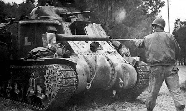 |
| An American tanker cleans the 75mm gun of a M3 Medium Tank in Tunisia during the winter of 1942-43. |
 |
| The Grant I was a M3 Medium Tank with a new turret according to British requirements. |
 |
| Standard M3 Medium Tanks were referred to by the British Army as a Lee I. Sandbags were installed to provide additional protection to the rather thin armor on the production vehicles in the Middle East. |
 |
| A Soviet M3 Medium Tank destroyed on the Eastern Front in the summer of 1943. The tank was not particularly popular with the Russians because of its obsolete weapons arrangement. |
 |
| M3 Medium Tank first pilot, at Aberdeen Proving Ground, March 1941. |
 |
| Grant Medium Tanks in British service under repair in a workshop. Nearest vehicle is T26084, "A11." |
 |
| Comparison photo of M3 Medium Tank and pilot model of M4A1 Medium Tank (minus armament). |


No comments:
Post a Comment