Viewing Photographs

Many of the images used in this blog are larger than they are reproduced in the article posts. Click on any image and a list of thumbnails will be displayed and clicking on a thumbnail will display that image in its original size.

Yakovlev Yak-4 (BB-22): Soviet Reconnaissance Aircraft

Production Yak-4.


by Paul Roland

In 1938 a design collective headed by A. S. Yakovlev completed work on the streamlined BB-22 two-seat aircraft. It was their first twin-engined aircraft originally intended for a high-speed high-altitude reconnaissance role but then it was decided to also use this aircraft for short-range bombing missions. In the spring of 1939 the BB-22 made its first flight and it was immediately accepted into Soviet Air Force use.

The BB-22 was of mixed construction. The two longeron scheme wing was wooden with a veneer covering and was built onto the fuselage center section. The forward fuselage and pilot’s cabin with sliding canopy was duralumin pipe with a covering of plywood and the tail boom section with the observer’s cabin situated low in the middle of its front was chrome pipe with a linen covering. The horizontal tail and fins were wooden. The ailerons and tail unit flaps were duralumin with a linen covering. The tail unit was enlarged so as to increase the aircraft’s useful range by the addition of a half-sphere at the rear of each rudder.

This aircraft was capable of short takeoff since the weight was about 5 tons. There were two M-103 engines of 960 horsepower which provided a maximum flight speed of 567 kilometers per hour which was more than that of any fighter or two-engined aircraft of that time. It was almost 150 kilometers per hour faster than the twin engine SB (ANT-40) bomber. Beneath each engine nacelle was a pair of landing gear doors, made of duralumin, which opened to an angle of 50 degrees. The undercarriage was a retractable three-wheel scheme. In winter time use the wheels were replaced by skis.

Control of the rigid rudder for altitude and the ailerons were operated by means of a handle located in the pilot’s cabin. The rudder was controlled by means of wires. The landing gear doors opened and closed by means of the same powered gears as the undercarriage. The undercarriage was hydraulically controlled with an electro-drive pump but this system could accidentally be opened by hand. Braking of the main wheels was pneumatic.

The fuel feed system for the engines was from six tanks: two in the fuselage behind the observer’s cabin and there were two in each wing between the longerons. The tanks, pipes and fittings were made of duralumin.

Each engine nacelle had an oil radiator located beneath the motor. At the rear of each motor was a water radiator for cooling which surrounded the motor’s cylinders. The cooling air passed around the motor by means of lateral slits and tunnels. This air exhaust was regulated at the rear of the nacelle by means of hydraulically-activated louvers. Each nacelle also contained a carbon dioxide fire prevention system.

For defense against attacking aircraft a machine gun was installed in the nose in addition to the rear cabin’s dorsal machine gun but the cumbersome protective screening increased the aircraft’s weight. (It was later discovered that these guns were not sufficient as armament.) The nose mounted gun was also to be used for ground attack purposes. To prepare the dorsal machine gun for firing the observer had to remove his canopy and the fabric-covered upper part of the fuselage—that part from his canopy to the horizontal tail structure—had to be lowered into the fuselage tail boom’s lower part. The 400 kilograms load of four to eight bombs and its suspension system also increased the take-off weight.

An unarmed transport or cargo version, also used for liaison duties, of the BB-22 was flown but its performance was not satisfactory.

A modification of the reconnaissance/ bomber/attack aircraft’s cabin area into a large bulged “greenhouse” and deletion of the forward machine gun (one report says that this gun was retained with another machine gun mounted beside it), to improve aerodynamics and to decrease the loaded weight, in 1941 resulted in an aircraft bearing the new appellation of Yak-4. Each single main wheel was replaced by a two-wheel assembly, partially retractable, to support the strengthened airframe with new M-105 engines. Supplementary equipment, including underwing bombs and dive brakes, produced rather poor flying characteristics in the Yak-4.

This aircraft entered service in 1941 but in the following year the Yak-4 was found to be fulfilling a ground attack role for which it was not suitably armored and there were other newer light bombers. Therefore, after six hundred aircraft of the BB-22/Yak-4 series was manufactured since 1940, it was delegated to high-altitude reconnaissance and it was replaced in the fighter-bomber role by the more powerful, constructed of duralumin, Pe-2 dive bomber.

BB-22

Year of first flight: 1939

Length: 10.17 meters

Wingspan: 14 meters

Wing area: 32 square meters

Crew: Two

Take-off weight: 5,200 kilograms

Armament: Two ShKAS 7.62mm machine guns

Bomb load: 400 kilograms

Powerplants: Two Klimov M-103 liquid-cooled in-line

Power: 960 horsepower

Maximum speed: 567 kilometers per hour

Range with bomb load: 800 kilometers

Range without bomb load: 1,600 kilometers

Service ceiling: 8,800 meters

Yak-4

Role: Light bomber

Manufacturer: Yakovlev

Designer: Alexander Sergeyevich Yakovlev

First flight: 20 February 1940

Introduction: 1941

Retired: 1945

Primary user: VVS

Number built: 90

Developed from: Yakovlev Yak-2

Length: 10.17 meters

Wingspan: 14 meters

Wing area: 32 square meters

Crew: Two

Take-off weight: 5,200 kilograms or 5,845 kilograms

Armament: One or three ShKAS 7.62mm machine guns

Bomb load: 400 kilograms (minimum); 600 kilograms (maximum)

Powerplants: Two Klimov M-105 liquid-cooled in-line

Power: 1,100 horsepower

Maximum speed: 574 kilometers per hour

Speed at 5,000 meters: 540 kilometers per hour

Range with bomb load: 800 kilometers

Range without bomb load: 1,600 kilometers

Maximum altitude: 11,000 meters

Author’s Note

No clear definition is made between the BB-22, Yak-2 and Yak-4 in any book used by this author for reference. Therefore, the author assumes the following to be correct:

The BB-22 was the manufacturer’s designation of the Yak-2 “prototype.” The Yak-22 underwent cabin, airframe, bomb carrying, etc., modifications so as to become the Yak-4.

Any photo showing a military aircraft bearing Soviet markings which is captioned as an aircraft of the Red Air Force either shows an aircraft used by the nation of the Soviet Union or the photo caption is incorrect. The Soviet Army may be called the Red Army (even the Soviet press uses that title) but the USSR’s military aeronautical fleet is—and must be—referred to as the Soviet Air Force.

Publisher’s Note

According to Russian Aircraft Since 1940 by Jean Alexander (Putnam & Co., Ltd., London, 1975), this aircraft was A. S. Yakovlev’s first military design. It was designated the Ya-22 (the manufacturer’s designation was AIR-22). It was completed in early 1939. Initial tests were so successful that it was put into production immediately as the BB-22 (Blizhnyi Bombardirovshchik = short-range bomber) although it had been originally designed as a long-range fighter-reconnaissance aircraft with the designations I-29 for the fighter version and R-12 for the reconnaissance version. It later received the designation Yak-4.

Bibliography

Kondratbev, V. Modellist Konstruktor. [Soviet magazine] Moscow, 1976.

Nemecek, Vaclav. Sovetska Letadla. Nase Vojsko, Prague, 1969.

Nowarra, Heinz J. Die Sowjetischen Flugzeuge 1941-1966. J. F. Lehmanns Verlag, Munich, 1967.

Nowarra, Heinz J. and G. R. Duval. Russian Civil and Military Aircraft 1884-1969. Fountain Press Ltd., London, 1970.

Simakov, B. L., editor. Airplanes of the Land of the Soviets 1917-1970. Voluntary Society for Assisting Air Force, Army and Navy Publishing House, Moscow, 1974.

Taylor, John W.R., editor. Combat Aircraft of the World From 1909 to the Present. G. P. Putnam’s Sons, New York, 1969.

Yakovlev, A. S. Soviet Aircraft. Science Publishing House, Moscow, 1975.

Yakovlev Yak-4.

 
The prototype BB-22. The fuselage and engine nacelles are red, the wings and tails are white with the rear of the rudder painted in the traditional A. S. Yakovlev red/white stripes. Each propeller was polished natural duralumin. However, the wartime operational Yak-4 bore the usual Soviet Air Force camouflage color scheme.

A production Yak-4 in flight shows the similarity of the wing design to that of the Yak-1 fighter.

The Yakovlev Yak-4 production version had glycol radiators in the rear of the nacelles and chin-type oil cooler intakes. The rear fuselage was fabric covered.

Production Yakovlev Yak-4.

Production Yakovlev Yak-4.

Yakovlev Yak-4.

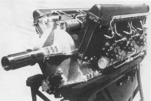
The M-105 engine of the BB-22bis #1002 airplane.

Experimental BB-22bis with M-105 engines.

The first prototype, the Samolot 22.

The first prototype, the Samolot 22.

The first prototype’s engine, Samolot 22.

BB-22.

BB-22 with ski undercarriage.

Production Yak-4.

Production Yak-4.

Production Yak-4.

Production Yak-4.

Production Yak-4.

Yak-4, early in Barbarossa campaign.

Production Yak-4.

Production Yak-4.

Production Yak-4.

Production Yak-4.

Production Yak-4.

Production Yak-4.

Production Yak-4.

Production Yak-4.

Production Yak-4.

Production Yak-4.

Production Yak-4.

Production Yak-4.

Production Yak-4.

Production Yak-4.

Production Yak-4.

Production Yak-4.

Yak-4 engine.

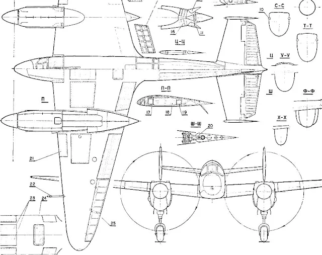
Yak-4. The following information and three-view drawing (note split plan view) are courtesy of B.C.F. Klein. Type: Two-seat short-range light bomber and high-altitude reconnaissance aircraft. Powerplants: Two 1,100 hp M-501R in-line engines. Armament: Two fixed forward-firing 7.62 mm ShKAS machine guns in the nose and one flexible rearward-firing 7.62 mm ShKAS machine gun for the observer; plus eight 55 lb. bombs internally and four 220 pound bombs on wing racks. Maximum speed: 352 miles per hour. Wingspan: 45 feet 11 inches. Length: 33 feet 4.5 inches.

Yakovlev Yak-4.

BB-22 Drawings: This and the next three drawings are from Modellist Konstruktor magazine and show the aircraft in plan views, plus various detail views (propeller, cockpit and rear cabin views, undercarriage views, and landing flap mechanism), and sectional views of the fuselage. The drawings were prepared by V. Kondratbev from a restored BB-22.

BB-22.
Key to BB-22 Plan Drawings
This is a list of the numbered parts on the drawings as translated by the author.
1. Air intake for oil radiator
2. Intake pipe for engine
3. Bar for rudder turning
4. Removable front fairing
5. Sliding portion of lighted pilot’s cabin
6. Eight 20 kg photo bombs
7. Aperture for hoist
8. Storage battery hatch
9. Strut of tail boom to fuselage
10. Engine exhaust pipe
11. Water radiator access
12. Landing flaps
13. Bending hinge plate for aileron
14. Control arm for aileron
15. Aileron rocker
16. Water radiator
17. Front of wing spar
18. Fuel tank
19. Rear of wing spar
20. Type of bending hinge plate for rudder elevation and depression
21. Oil tank
22. Aerial pressure receiver
23. Bomb bay
24.    Navigation vision slit hatch (perhaps used for repair work)
25. Aileron section (gently closing panel)
26. Front fuselage strut
27. Cartridge box
28. Instrument panel for pilot
29. Front gunsight
30. Protective cushion for gunsight
31. KPA-36is oxygen apparatus
32. Control wheel for elevator elevation
33. Engine control lever
34. Control handle for retraction of undercarriage
35. Machine gun belt feed pipe
36. Control handle
37. Machine gun cartridge case outlet
38. Machine gun belt ejection outlet
39. ShKAS machine gun
40. Handle to recharge machine gun
41. Control handle for landing flaps
42. Oxygen tank
43. Left desk for pilot
44. Pilot’s cockpit floor (corrugated)
45. Steering handle for alignment of water radiator
46. Right desk for pilot
47. Instrument panel for navigator
48. Horizontal panel
49. AFA aerial camera
50. Navigator’s cockpit floor
51. Hammock seat
52. Power-driven bomb release gear
53. Cartridge case outlet
54. ShKAS turret machine gun
55. Fastening bracket for machine gun
56. Machine gun belt feed pipe
57. Hydraulic jacks for control of landing flaps
58. Synchronization bar
59. Guide roller
60. Guide
61. Cross bar
62. Joint
63. Lock for opened tail wheel position
64. Hydraulic jack for retracting tail landing gear
65. 300 x 125 mm wheel
66. Engine nacelle girder
67.    Hydraulic jack for retracting main undercarriage arm
68. Brake hose
69. 600 x 250 mm wheel
70. Rearwards folding strut
71. Undercarriage door

BB-22.

BB-22.

The first prototype.

BB-22.

BB-22bis.


Production Yak-4.

Production Yak-4.

U.S. Navy Squadron Insignia


Budd RB-1 Conestoga: American Transport

A Budd RB-1 Conestoga, BuAer 39294, loading a Navy ambulance, displays the ease with which it could be loaded. 


by Leo Kohn

There probably aren't many Budd Conestogas left in the world today, but it set the pace in 1942 for the true all-cargo airplane and its various features are commonly seen today in almost all of the huge cargo planes.

The Edward A. Budd Company of Philadelphia was awarded a contract by the U.S. Navy in 1942 to develop and manufacture a pure cargo transport of stainless steel construction. The concept of cargo carriers was being radically altered through need and experience from the swift aerodynamically clean de­sign to slower, more lumbering and capacious craft designed for a specific pur­pose and not merely adapted from existing types. For up to World War II the cargo airplane was basically a conversion of the conventional airliner. Even by widening the doors, it was still difficult to load larger items, not to mention the fact that everything had to be lifted into them.

Budd specialized in welded stainless steel products, and had ten years previously built a stainless steel amphibian under the direction of Anea Bossi of American Aeronautical Corporation. The airplane, based closely on the American Marchetti S-56, was subjected to accelerated service tests, and was demonstrated on three continents. Later, it became part of the exhibits of the Franklin Institute in Philadelphia.

The engineers at Budd centered their efforts on the problem of designing a "flying box car," something that could carry freight economically on a flight of moderate length, and also be capable of loading and unloading cargo with ease and dispatch. A large cargo hatch in the aft underbody could be lowered to form a ramp to the surface of the airfield, or brought to the level of a loading dock or truck bed. The clearance doors could be lifted out of the way to pro­vide the necessary headroom to get large objects inside. The cargo com­partment would be 26 feet in length, 8 feet 8 inches wide, and 10 feet high.

Weight saved by welding rather than riveting, and economies effected by us­ing thinner sheets of stronger material made up for the weight difference be­tween it and aluminum. The stainless steel was ribbed in such a way as to make the airplane seem covered with a wrinkled, warty skin.

The airplane was designated the RB-1 by the Navy and named the Cones­toga for the covered freight wagon that moved our ancestors and their be­longings across the plains to the Pacific a century ago. The Navy accepted the design early in 1942 and in May of that year construction began at the Budd Field plant. A formal contract for two hundred RB-1's was awarded in August 1942, and the first airplane flew on 31 October 1943. The static test ship was com­pleted on 12 August, and those tests were finished on 17 October.

With an especially heavy load, the Conestoga could carry it 650 miles. It demonstrated that in normal operations it could lift 10,400 pounds of payload off a landing strip after a run of only 920 feet. It could be converted to a troop or hospital ship; provisions were made for installation of twenty-four seats or twenty-four stretchers. Doors on both sides of the fuselage permitted jumping of paratroops from both sides simultaneously, and cargo could be discharged via parachute through the opened clearance doors in the back of the fuselage.

The wing did not pass through the fuselage in conventional fashion. Instead, Budd engineers were able to attach the wing panels to side frames joined across the body by shallow but rigid transverse members, thereby providing headroom of 2½ feet more than otherwise would have been possible.

A specially designed hoist fitted above the loading ramp and a manually op­erated winch mounted at the forward end of the cargo bay made the loading of heavy pieces no great problem. The large loading entrance could accommodate jeeps, small landing craft, trucks, and field artillery. The power to lift all this was provided by two Pratt & Whitney R-1830-92 Twin Wasps of 1,200 horsepower each.

The Army Air Forces became interested in the airplane and placed a con­tract for six hundred, these to be designated as the C-93A. However, delays in produc­tion resulted in a reduction of the Navy order to twenty-five airplanes, these assigned Bureau of Aeronautics serial numbers 39292 through 39317. Cancellation of the Army contract followed shortly on the heels of the Navy contract reduction.

With only twenty-five aircraft of this type it was impractical to keep them on the active list, and they were declared surplus in early 1945. Bob Prescott, an origi­nal member of the AVG Flying Tigers, persuaded eleven of his Tiger colleagues and five Los Angeles businessmen to put up $226,000 to buy fourteen Conestogas. Headquarters was set up at Long Beach in June 1945 and The Flying Tiger Line, Inc., was in business.

Weeks passed while the Tigers convinced cautious shippers to give air freight a try. It was touch and go for the line, more touch than go. In fact, there was so little cash in the till after the purchase of the Conestogas that the Tigers were only able to bring one plane to the West Coast. The remaining Budds were left grounded in Augusta, Georgia, until such time as there was enough cash to purchase gasoline. Eventually gasoline was purchased, and the Conestoga created the huge air-freight line that Flying Tiger became. Sev­eral of the other surplus RB-1's went to Central American operators where they might still be flying.

Span: 100 feet

Length: 68 feet

Height: 31 feet 9 inches

Wing area: 1400 square feet

Empty weight: 20,156 pounds

Gross weight: 33,860 pounds

Maximum speed: 197 miles per hour at 7500 feet

Cruise speed: 165 miles per hour

Normal range: 1,700 miles (3,500 miles with auxiliary tanks)


Budd RB-1 Conestoga transport, seen after the war in civilian service.

Budd RB-1 Conestoga (as civilian NC-45354), Oakland, 1 September 1948.

Budd RB-1 Conestoga.

Budd RB-1 Conestoga in three-tone Navy scheme.

Budd RB-1 Conestoga in three-tone Navy scheme.

Budd RB-1 Conestoga in three-tone Navy scheme.

Budd RB-1 Conestoga.

Budd RB-1 Conestoga.

Budd RB-1 Conestoga.

Budd RB-1 Conestoga.

Budd RB-1 Conestoga all-stainless-steel transport aircraft in flight.

Budd RB-1 Conestoga.

Budd RB-1 Conestoga.

Sally Siebert from the Women Accepted for Volunteer Emergency Service (WAVES) and Winifred Thompson from the Women's Army Corps (WAC) pose for a publicity photo with a Budd RB-1 Conestoga cargo aircraft at Budd Field, Philadelphia, Pennsylvania, 29 January 1945.

Budd RB-1 Conestoga flown by The Flying Tiger Line (originally named National Skyway Freight), which was formed by Robert W. Prescott and ten former members of the AVG "Flying Tigers" group in 1945.

Budd RB-1 Conestoga.

View of the inside of hanger two at the U.S. Naval Air Station South Weymouth, Massachusetts (USA), on 14 September 1944. Visible are five blimps and the following aircraft: circa 60 Grumman F6F Hellcat fighters; seven North American SNJ Texan trainers; one Douglas SBD Dauntless dive bomber; two Lockheed PV-1 Ventura patrol bombers; one Budd RB-1 Conestoga transport (lower left corner); circa 12 Beechcraft SNB/JRB Navigator/Kansan, at least three of them being SNB-1 gunnery trainers; one Lockheed R5O Lodestar transport; two Howard GH Nightingale trainers.

Budd RB-1 Conestoga at the Pima Air Museum.